Differentiate Between Ucs And Wcs In Autocad
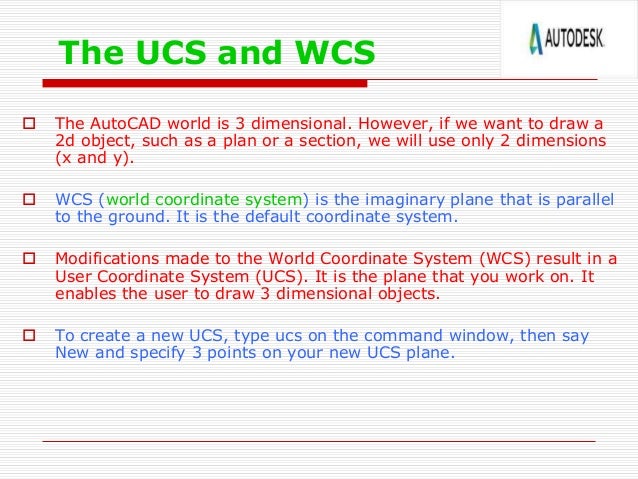
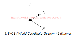
By Every point in an AutoCAD drawing file can be identified by its X,Y,Z coordinates. (In most 2D drawings, the Z-coordinate value is 0.0.) This system of coordinates is referred to in AutoCAD as the w orld c oordinate s ystem, or WCS.
Change Ucs In Autocad

Coordinate input The most direct way to enter points precisely is to type numbers with the keyboard. AutoCAD uses these keyboard coordinate entry formats:. Absolute Cartesian (X,Y) coordinates in the form X,Y (for example, 7,4).

Relative X,Y coordinates in the form @ X,Y (for example, @3,2): Defines a new point that is X units horizontally and Y units vertically away from the current point. Relative polar coordinates in the form @ distance ): The status bar coordinate readout is dimmed, and the coordinate values don’t update until you pick a point.
On, showing X,Y coordinates ( ): The coordinate readout appears black, and the absolute X,Y coordinates update continuously as you move the crosshairs. If no command is active, clicking the coordinates readout alternates between this mode. On, showing polar coordinates ( ): This mode, which displays distance and angle relative to the last point picked rather than absolute X,Y values, appears if a command is active and AutoCAD is waiting for you to pick a point.

On, showing geographic coordinates ( ): This mode displays coordinates as latitude and longitude values, but it can be used only after you set the drawing’s geographic location with the GeographicLocation command. If you start a command such as Line, pick a point, and then click the Coordinates area a few times, the display changes from coordinates Off to live absolute coordinates to live polar coordinates. Displaying live polar coordinates is the most informative mode most of the time. If you’re working in AutoCAD’s architectural or engineering units, the default unit of entry is inches, not feet.
Here are some guidelines for entering numeric values when you work with feet and inches:. To specify feet, you must enter the apostrophe ( ′) symbol for feet after the number: 6′ is 6 feet. To separate feet from inches, enter a dash: 6′-6″ is 6 feet, 6 inches. When you enter coordinates and distances, both the dash and the inch mark are optional: 6′6″ and 6′6 are the same as 6′-6″. To type a coordinate or distance that contains fractional inches, you must enter a dash — not a space — between the whole number of inches and the fraction: 6′6-1/2 (or 6′-6-1/2) represents 6 feet, 6-1/2 inches. To enter partial inches, use decimals instead: 6′6.5 is the same as 6′6-1/2″ to AutoCAD, whether you’re working in architectural or engineering units.